Local coordinate systems
In CADMATIC Plant/Outfitting, all new projects have a default coordinate system named "Project". This root coordinate system, which all other coordinate systems are defined in relation to, has no rotation or translation and cannot be modified. If a project contains constructions that are aligned differently from others, the project administrator can define any necessary local coordinate systems. These additional coordinate systems can deviate from the root coordinate system in origin and rotation.
Getting started
Upgrading from an older version
CADMATIC versions older than 2020T3 did not support local coordinate systems and therefore do not have the Project coordinate system either.
When upgrading from an older CADMATIC version, the CADMATIC desktop command Object > Upgrade Project Environment must be run because it updates all the existing design areas to use the Project coordinate system. After the conversion, also local coordinate systems can be added.
Note the following:
-
Model objects and documents that existed before the upgrade do not have an explicit coordinate system reference, as described in Model object data and Documents and local coordinates, respectively.
-
Model queries that reference the object's geometry should be run in the coordinate system in which they were created, as described in Model queries.
Installing a backup or unarchiving a project
Backups and project archives created in CADMATIC versions older than 2020T3 do not have the Project coordinate system.
When installing a backup or unarchiving a project, the program automatically creates the Project coordinate system if it is missing from COS.
Creating a local coordinate system
Initially, a CADMATIC project only contains the Project coordinate system. To enable the 3D designers to model constructions that are within the project space but require some rotation or translation, the project administrator can create one or more local coordinate systems that are relative to the root coordinate system. Creating of local coordinate systems is described in Coordinate Systems.
Using a local coordinate system
If the project contains local coordinate system definitions and the user is creating a new Plant Modeller application area, Service Instance, or Agent, the program prompts the user to select which coordinate system to use, and to define the limits of that design area within the project space.
In the Plant Modeller application, the user can also adjust the limits of the design area later and see how the new limits are positioned within the project space, as described in Set limits and save.
Plant Modeller also allows the user to move objects from the current coordinate system to another, and to color the objects in the work views based on their coordinate system, as described in Local coordinates.
The Object properties dialog and the Properties pane show the coordinate system of the selected object.
Model objects and local coordinates
There are some COS objects, such as groups, that do not have a reference to a coordinate system. Model objects and model queries, however, are linked to coordinate systems, as described below.
Model object data
Model objects store a COS-level reference to the coordinate system that they belong to.
The object data, which stores geometric information such as positions and directions, is stored relative to the local coordinate system.
The COS bounding boxes are stored in the Project coordinate system.
If the project has been created in an older CADMATIC version that did not support local coordinates, any model objects that existed before the version upgrade do not have an explicit reference to a coordinate system, but implicitly belong to the Project coordinate system. If they should belong to a local coordinate system, the user can move them in Plant Modeller as described in Change coordinate system.
Model object ownership
Plant Modeller commands that attempt to get the ownership of the object, such as Check Out and Request Ownership, require that the targeted object belongs to the coordinate system that is currently being used.
Plant Modeller commands that give away the ownership of the object, such as Check In, Cancel Check Out and Relinquish Ownership, only work on objects that already belong to the user, so also they require that the objects belong to the current coordinate system.
Plant Modeller commands that control access, such as Force Cancel Check Out and Take Ownership, work on all objects regardless of their coordinate system reference.
Model queries
Model query COS objects store a reference to the coordinate system in which they were created.
Model queries that contain bounding box tests and other tests that relate to object geometry should only be run in the coordinate system in which the model query was created. This is because in geometry-related tests the results are different when the coordinate system is not the same.
Model queries that do not contain tests that relate to object geometry will provide the same results in all coordinate systems.
Documents and local coordinates
Documents store a reference to the coordinate system in which they were created, and they are also coordinate system specific. That is, unlike model objects, documents cannot be moved from one coordinate system to another. Documents can only be edited in areas that are in the same coordinate system as the document itself.
If the project has been created in an older CADMATIC version that did not support local coordinates, any documents that existed before the version upgrade do not have an explicit reference to a coordinate system, but implicitly belong to the Project coordinate system.
Pipe/duct main documents and spools
Documents that belong to a main document are always assigned to the same coordinate system as the main document.
Piping isometrics and spools
Piping isometric documents are assigned to the coordinate system in which they were created. The coordinate system is shown in the iso attributes. All geometry points are in the same coordinate system as the isometric.
Notice that the Center of Gravity attributes in the header are in the Project coordinate system.
The spools of the isometric are assigned to the same coordinate system as the isometric document.
Isometric drawings have their own coordinate system references at each coordinate system.
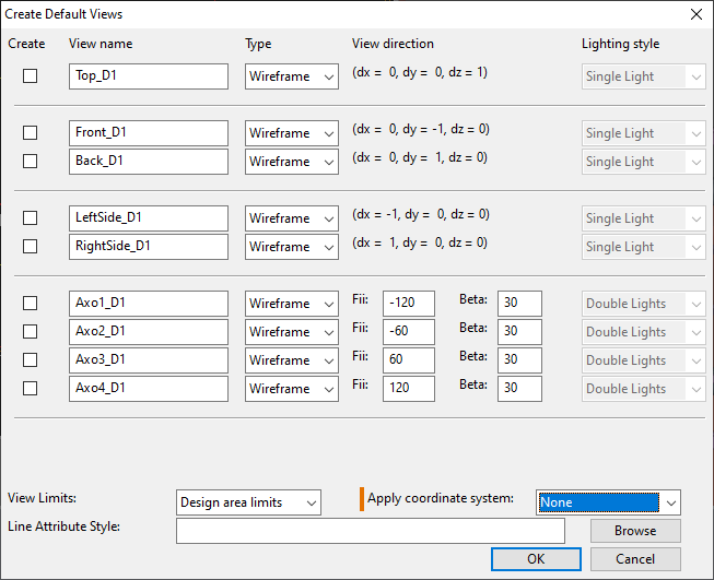
Drawing views
When creating a new drawing view in Plant Modeller, the user can apply transformation to the view by selecting one of the available coordinate systems. This allows the new view to show the objects using the perspective (viewpoint, view direction, and up-vector) of the specified coordinate system, which is especially useful when creating drawings whose associated views are in another coordinate system.
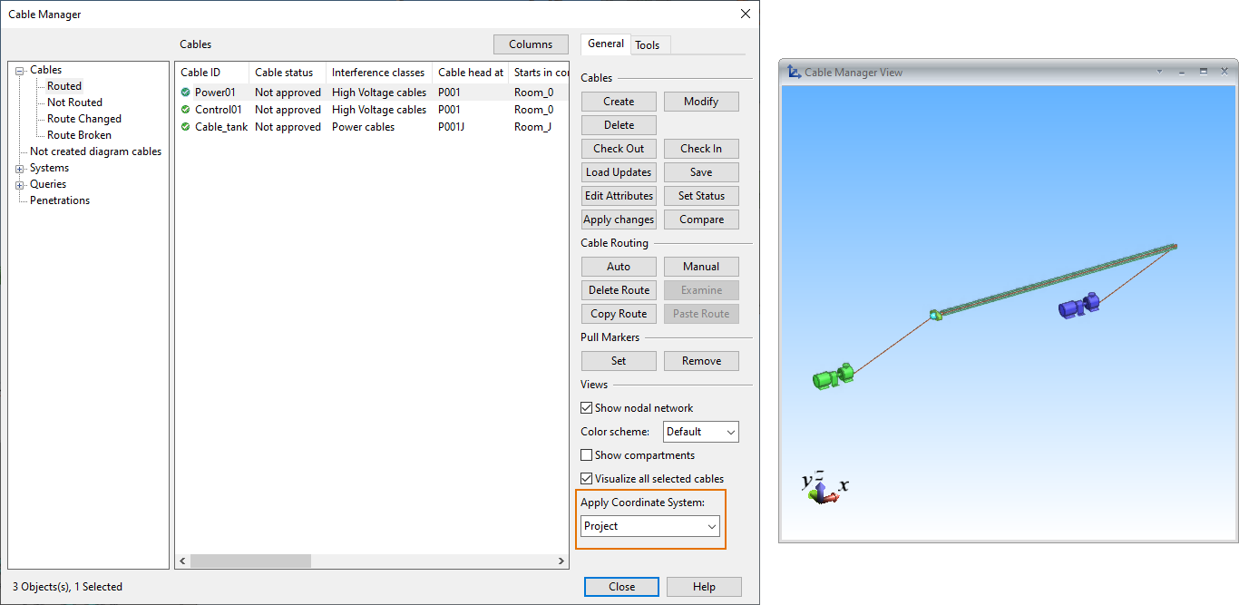
Cables and local coordinates
The Cable list pane and the Manager tool can only be opened in an area that covers the entire project space. In practice, this means that only areas that use the Project coordinate system instead of a local coordinate system can be used to manage cables.
However, in the Cable Manager dialog, the user can select one or more cables and then apply coordinate transformation to them by selecting one of the available coordinate systems. This shows the cables in the Cable View window according to the specified coordinate system, so that the designer can see how the cabling looks in that other coordinate system.
For general information on the cable router, see Cables.
COS and local coordinates
Partial replication
Currently, partial replication and local coordinate systems cannot be used at the same time.
-
If a project already has replication filtering boxes defined, new local coordinate systems cannot be created.
-
If a local coordinate system (other than the Project coordinate system) exists, new deny/allow boxes cannot be created.
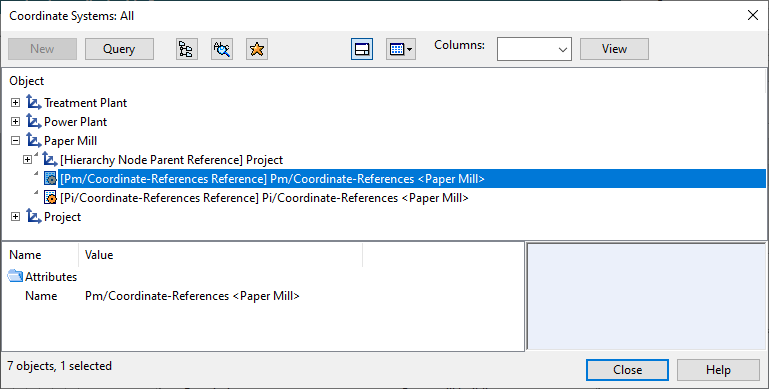
Coordinate system reference objects
Starting from release 2020T3, projects can contain multiple reference coordinate systems instead of just one, and the user should use the coordinate system that the design area is using. There are special reference objects in COS that define relations between different coordinate systems, and the names of these reference objects contain the name of the related coordinate system.
Import/export and local coordinates
CX export and import
When exporting objects using the CX export format, the export contains the associated local coordinate systems.
When importing a CX file that contains local coordinate systems, the importer determines whether the imported coordinate systems are new or match an existing one. An imported coordinate system is considered to be new if all the coordinate system parameters are not equal to an existing coordinate system's parameters.
MDL export and import
When generating MDL files, the COS OID of the area's active coordinate system is embedded into the MDL file.
When importing an MDL from a different area, the importer transforms the objects according to that area's coordinate system.
If MDL is exported from one project and imported to another project, then the active coordinate system embedded into the MDL file is not found. In this case, the MDL is imported to the active coordinate system.
3D-Import Manager
Imports that are managed using the 3D-Import Manager tool are local to the coordinate system they are created in. There are no local coordinates system transformations, neither in export nor import.
For general information on 3D-Import Manager, see Imports.
Sister projects and local coordinates
Currently, Sister Project Management and local coordinates cannot be used at the same time.
-
If a project is already related to a sister project, new local coordinate systems cannot be created.
-
If a local coordinate system (other than the Project coordinate system) exists, the sister project functionality cannot be used.
For general information on Sister Project Management, see Sister project tutorial.
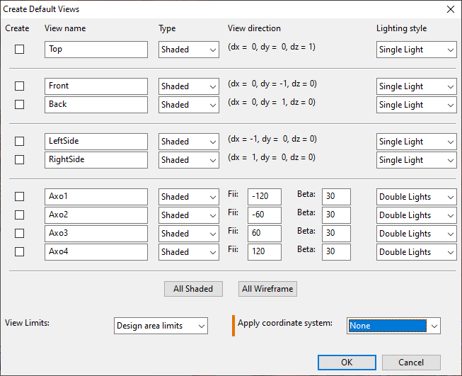
Work views and local coordinates
By default, the work views in Plant Modeller use the coordinate system of the area. However, when creating a new work view, the user can apply specific coordinate system transformation to it by selecting one of the available coordinate systems. This allows the new view to show the objects using the perspective (viewpoint, view direction, and up-vector) of the specified coordinate system.
For general information on view properties, see Set Properties of View.
Collision detection and local coordinates
Collision detection results should be investigated in the same coordinate system in which the collision detection results were computed. Otherwise, the collision result data might not be up-to-date.
For general information on collision detection, see Collisions.
Work requests and local coordinates
The standalone work request tool can process a work request from a local coordinate system when the Object ID of the local coordinate system is defined in a command-line parameter. You can get the OID from the Coordinate Systems tool—see Coordinate Systems.
Syntax:
<path to wrm_standalone.exe> -1 <application profile> -c <COS server hostname and port> -p <project name> -l <oid of local coordinate system>Example:
C:\Cadmatic\co203\pms2030.nt\wrm\wrm_standalone.exe -1 "C:/Cadmatic/co203/CadDtm.prf" -c MyPC-01:5060 -p LocalCoord.pms -l aL4oJblsIkYhwxiQvU114G